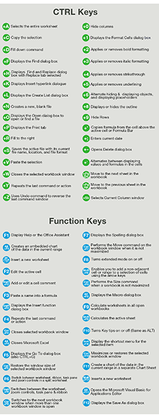

The Shortcut Bars tab can be used to modify the shortcuts available in the S key shortcut menu. Multiple hotkeys can be added if desired. Simply click in the Shortcut(s) cell for the command and type the keyboard shortcut to apply it. The Keyboard tab, shown above, can be used to modify existing shortcuts or create custom ones for any SOLIDWORKS command. The resulting dialog is shown below, and several tabs are available for customization. The tools found on this menu can be customized by right clicking on the menu once it has been activated and choosing Customize, or by simply clicking the options dropdown and choosing Customize. Since the menu is context-sensitive, different menus will be presented depending on whether the part, assembly, drawing, or sketch environment is active. This opens a context-sensitive shortcut menu for rapid access to your favorite commands. One exceptionally popular keyboard shortcut is the S key. A table of some of the most popular default SOLIDWORKS keyboard shortcuts has been provided below: Another great shortcut is CTRL-B, which will automatically rebuild your model. Pressing the R key will display a list of recent documents, and specific documents can even be pinned to the list permanently. However, many additional SOLIDWORKS-specific keyboard shortcuts exist that can make potentially tedious point-and-click commands obsolete.Ī few of the more popular shortcuts include using the spacebar to bring up the Orientation menu, which provides access to many standard views, as well as any custom views that have been saved. As expected, CTRL-O can be used to open a document, CTRL-S will save the current document, and CTRL-Z will undo the most recent action. While using SOLIDWORKS, all of the standard Microsoft keyboard shortcuts are available.
#Hotkeys for edrawings viewer 2016 how to
This article covers many of the most impactful default keyboard shortcuts in SOLIDWORKS, and describes how to customize them for maximum time savings. However, many users prefer to leverage a variety of both standard and custom shortcuts through hotkeys or context menus for an even faster workflow. Using the standard SOLIDWORKS tools and features from the CommandManager is already an extremely efficient method to quickly bring concepts into a three dimensional model. Tags: 3D CAD, 3D Design, 3D Modeling, continuity, curvature, SolidWorks, SOLIDWORKS 3D CAD And the curvature continuous stripes share the same direction and the same size throughout the entire surface. The zebra stripes for tangent have the same direction, but change sizes where the tangency occurs – there are two points of tangency. As can be seen in the image below, the zebra stripes for contact do not have the same direction or size. With zebra stripes, we can verify that two adjacent faces are in contact, are tangent, or have continuous curvature. This tool mimics the reflection of long stripes of light on a very shiny surface. The zebra stripes tool ( view>display>zebra stripes ) allows us to see small changes on a surface that may be hard to see with a standard display. Now we’ll be taking a look at some additional analyses tools to further evaluate our surfaces as well as ways to improve our curvature continuous connections. In Part I of this series, we looked at how the smoothness of curves can be analyzed and controlled. Tags: 3D Design, geometry, SOLIDWORKS 3D CAD To begin creating a plane, access the Features tab of the CommandManager, select Reference Geometry, and then click Plane. While offset options in the Extruded Cut command could be used to accomplish this, creating a plane tangent to the surface will be more robust, and will result in better design intent should the design be resized in the future.Īll types of reference geometry are considered features and can be found in the Features tab. In this example, a fly reel is being designed, and so far everything has been smooth sailing.Īt this point, we want to create a rectangular cut on one of the larger cylindrical surfaces of the fly reel, but there is no flat surface to create a sketch. In this article, we’ll cover the basics of creating planes, axes, and coordinate systems to help you throughout your design process. Reference geometry includes planes, axes, coordinate systems, reference points, the center of mass, and mate preferences. However, as the complexity of designs increases, it often becomes necessary to create and utilize reference geometry to produce models with appropriate design intent. Utilizing SOLIDWORKS Reference Geometry for Complex Designsįor basic SOLIDWORKS models, users can often complete designs by leveraging only the default planes and available model geometry.


 0 kommentar(er)
